Hydraulic
design of wastewater treatment plants
ARTS facilitates the
hydraulic design of wastewater treatment plants (WWTPs)
at two levels:
(a) the property pages for the individual treatment unit objects enable the user to carry out an internal hydraulic design of the treatment unit.
(b) the ANALYSIS menu has an HYDRAULIC PROFILE sub-menu that has been designed for the computation of hydraulic profiles across WWTPs.
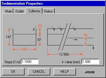
The procedure used for the hydraulic design of wastewater treatment plant process units consists of editing the sequence of property pages for the corresponding ARTS object, as illustrated for a sedimentation tank on (a) - (c ), inclusive. The sedimentation tank pictured here is a circular tank, with a peripheral weir composed of rectangular notches. These notches discharge into a collector channel which is 400mm wide.

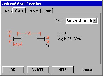
This example demonstrates a design feature of ARTS. ARTS automatically recalculates dependent parameters, in this case the overflow weir parameters are dependent on the Inflow and the tank diameter. If the user changes either of these ARTS recalculates the parameter values for the outlet weir, thereby always providing the user with an operable initial set of values.
The graphical user interface coupled with the ARTS Hydraulic Profile Analysis menu commands provide the user with a very flexible instrument for the hydraulic design of gravity flow systems such as WWTPs.
The treatment system may incorporate any of the following hydraulic objects on the tool palette:
activated sludge reactor, flume, pipe, biofilter, reservoir, detritor,
flow divider, screen, sedimentation tank, weir, channel
The flow can be split into multiple parallel streams using the flow-divider tool. The hydraulic effect of taking one stream out of operation for repair/maintenance purposes can be readily examined.
The system inflow range is defined by placing a flow graphic at the head of the system under consideration and editing the flow objects properties including Maximum flow, Minimum flow, Average flow and wastewater temperature. Subsidiary inflows and outflows to and from points along the system are also permissible.
The TWLs, which define the hydraulic profile
across the system, are computed with reference to a
user-input datum level at the outlet node of the system.
In computing head loss across the system, ARTS
automatically takes inlet and outlet head losses in the
linking pipes into account, as well as the local losses
at pipe junctions, where there is a change in diameter.
In addition, the user can edit the linking pipe property
pages to include fittings such as bends and valves, etc.
The ARTS Hydraulic Profile menu includes an Auto Design
command which can be used to generate an initial
treatment system, whose elements are capable of
transmitting the maximum flow. This design can then be
refined by the user by editing the property pages of the
component elements of the system.
An illustrative design sheet example of a 2-stream WWTP,
which incorporates screening, grit removal, flow
measurement, primary sedimentation, activated sludge and
secondary sedimentation, is shown below. The system
inflow is set to the range is 0.05 - 0.22 m3/s; the
system outlet TWL is set at 12.60 mOD. The activated
sludge recycle rate is set at 0.1 m3/s.
The screen display following execution of the Hydraulic
Profile/Auto Design and Hydraulic Profile/@ Max. Flow
commands from the Analysis menu is also shown. The former
of these two commands sets the sizes of all elements in
the layout so that they can take the maximum flow. The
latter command calculates the TWLs, starting at the
system outlet node, at which the TWL has been specified
as part of data input.

The two TWL values printed on each
treatment system object, following execution of the
Hydraulic Profile @ Max. Flow command, represent the
inflow zone TWL and the outflow chamber TWL,
respectively. These spot values define the hydraulic
profile across the treatment system, as well as setting
the elevations of the treatment units relative to the
outlet level.
Corresponding screen outputs can be obtained for the
minimum and maximum flows by executing their respective
Hydraulic Profile commands.
Execution of the Hydraulic Profile commands sets the pipe
end node elevations to comply with the node submergence
condition, as specified on the nodes property pages. The
default setting for pipe nodes is fully submerged at all
flow conditions. This can be altered to a free discharge
in certain cases.
The hydraulic profile at maximum and minimum flows for
single stream wastewater treatment systems can be
plotted, as illustrated to the right.